Reading a BIOS chip with a CH341A programmer: a careful first recovery
A bad BIOS flash used to mean a dead board, or a hunt for someone with an EPROM burner. Today a USB programmer built around the WCH CH341A chip and a spring clip will read and rewrite most SPI BIOS chips without the board even powering on. It is the tool that turns a failed microcode edit into a short evening instead of a landfill trip. It also has a known electrical flaw, and most of the care in this guide goes into working around it.
What is actually on the board
Most desktop boards from the late 2000s on keep their BIOS in a serial NOR flash chip on the SPI bus (a simple four-wire serial link: clock, chip select, data in and data out). People call them 25-series chips, after the part numbers most makers use (25Q64, 25L8005 and so on), and on desktop boards they usually come in an eight-pin SOIC package, a small black rectangle with four gull-wing legs on each side. A dot or notch marks pin 1.
The pinout is standard across makers. Winbond's W25Q64FV datasheet gives it for the 8-pin SOIC:
| Pin | Signal | Pin | Signal |
|---|---|---|---|
| 1 | /CS (chip select) | 8 | VCC |
| 2 | DO (data out) | 7 | /HOLD |
| 3 | /WP (write protect) | 6 | CLK |
| 4 | GND | 5 | DI (data in) |
Sizes are given in megabits, so divide by eight for bytes. A 25Q64 holds 64 Mbit, which is 8 MB or exactly 8,388,608 bytes. Many Core 2 era boards use smaller parts: an 8 Mbit chip holds 1,048,576 bytes. Remember that number, because the size of every dump and every image you write must match it to the byte.
Some older boards use a socketed PLCC32 chip on the LPC or FWH bus instead. The CH341A does not talk to those buses, so this guide does not apply to them.
The CH341A kit and the SOIC8 clip
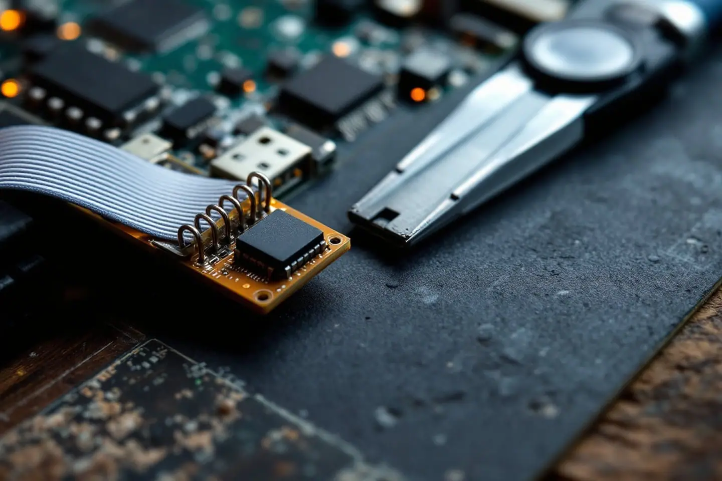
The common kit is a small board with a USB plug, a ZIF socket printed with "24" and "25" rows (for I2C EEPROMs and SPI flash), a SOIC8 test clip on a short ribbon cable, and an adapter board that maps the clip to the ZIF socket. The clip pinches the chip's legs, so you can read it in place. flashrom's manual notes that its CH341A driver takes no parameters and runs SPI at a fixed 2 MHz. That is slow, but flashrom's wiring notes point out that slower clocks are more forgiving of poor connections.
The ribbon cable's red wire marks pin 1 by convention. Line it up with the dot on the chip. A clip on backwards puts VCC and ground on the wrong legs, so check it twice with the magnifier before you plug in USB.
The 5 V signal problem
This part is community knowledge rather than anything WCH documents for these boards, but it is well established. On many of the black CH341A boards, the CH341A chip itself runs from the 5 V USB supply while the flash socket gets 3.3 V from a small regulator. The thread that documented it on the EEVblog forum in 2017 found that, as a result, the SPI signal lines swing to 5 V while the memory is powered at 3.3 V, with no series resistors to limit current. The Libreboot project's SPI documentation warns about the same thing and refuses to document the unmodified programmer for that reason.
Why it matters: Winbond's datasheet gives an absolute maximum of VCC plus 0.4 V on any pin. With the chip at 3.3 V, that is 3.7 V. Five volts is well past it, and the datasheet says exposure beyond absolute maximum ratings may cause permanent damage. Plenty of chips survive anyway, which is why the cheap boards keep selling, but in-circuit the same lines also reach the chipset.
What owners do about it, in order of effort:
- Measure first. With the programmer on USB, put a multimeter between ground and the CH341A chip's supply pin (pin 28 on the schematic posted in the EEVblog thread). If it reads about 5 V, your board has the problem. Libreboot notes that the green version of the board may already be wired for 3.3 V logic or have a voltage switch.
- Use a level-shifting adapter. Adapters that sit between the programmer and the clip translate the signals to 3.3 V or 1.8 V. Libreboot suggests a logic level converter as the flexible option.
- Do the 3.3 V mod. The fix discussed in the EEVblog thread lifts the CH341A's VCC pin and wires it to the chip's 3.3 V pin and the regulator output, so the whole chip runs at 3.3 V. It is a small soldering job on a fine-pitch pin. Libreboot adds that the /WP and /HOLD pins on these dongles are tied straight to 3.3 V, and recommends pull-up resistors instead.
Check the chip's voltage before anything else
Not every 25-series chip is a 3.3 V part. Laptops and some later boards use 1.8 V flash, and a 3.3 V programmer will damage it. The difference can be a single letter. Winbond's datasheets give these top-side markings and supply ranges:
| Top marking | Part | Supply range |
|---|---|---|
| 25Q64FVSIG | W25Q64FV | 2.7 to 3.6 V |
| 25Q64FWSIG | W25Q64FW | 1.65 to 1.95 V |
Read the marking with a magnifier and a raking light, search for the maker's datasheet, and find the supply voltage on its first page. Macronix, GigaDevice, EON and others follow the same idea with their own suffixes, so look up every part rather than guessing from the family name. A 1.8 V chip needs a 1.8 V adapter between the programmer and the clip, never the bare programmer.
We chose these from specifications and published reviews, not our own bench time. For the programmer, look for a listing that states its I/O voltage or includes a voltage selector, and buy a 1.8 V adapter only if your chip needs one.
Software: flashrom and the Windows tools
On Linux, flashrom is the reference tool and is packaged by most distributions. The CH341A uses the ch341a_spi programmer driver and talks over libusb, so it can run as a normal user once device permissions are set; running with sudo is the quick alternative.
Probe first, without reading or writing anything:
flashrom -p ch341a_spi
flashrom should name the chip and its size. If it reports several possible chips, it asks you to pick one with -c and the name exactly as flashrom -L lists it. If it finds nothing, reseat the clip before trying anything else.
Then read the chip twice, into two files, and compare them:
flashrom -p ch341a_spi -r dump1.bin
flashrom -p ch341a_spi -r dump2.bin
sha256sum dump1.bin dump2.bin
ls -l dump1.bin dump2.bin
The two hashes must be identical and the file size must equal the chip size you worked out from the marking. flashrom's own notes list inconsistent reads as the typical symptom of a poor connection or a setup that is not electrically clean. If the hashes differ, the files are worthless: reseat the clip and read again until two in a row match. Copy the good dump to two places off the machine before you go further.
On Windows, the community tools are AsProgrammer, an open-source project hosted on GitHub, and NeoProgrammer, a freeware tool passed around on forums. Both need WCH's CH341 driver, from the chip maker's own site. They work, and the same rules apply: read twice, compare checksums (certutil -hashfile dump1.bin SHA256 in a command prompt), and check the size. If you are not used to command prompts, our guide to opening a command prompt in a folder saves some typing.
In-circuit reads versus desoldering
Clipping onto the chip in place is the easy way, and on many boards it just works. The trouble is that the programmer feeds 3.3 V into the chip's VCC pin, and on the board that pin also connects to the chipset. flashrom's in-system programming notes describe the result: parts of the chipset power up partially from the programmer, start talking on the same bus, and either drag the voltage down or interfere with the read. Intel chipsets with a Management Engine are named as a particular problem because the ME uses the flash too.
Signs you are fighting the board rather than the chip: the probe finds nothing or a different chip each time, reads differ, or the programmer's supply sags. flashrom's ISP page lists workarounds, such as powering the board from its own supply and holding it in reset, or disconnecting the 12 V CPU connector. Those are for people comfortable with them. The plain alternative is to desolder the chip with hot air, read it in the ZIF socket through the SOIC8 adapter, and solder it back (or solder in a socket for next time). A few boards also have an SPI header for exactly this job; check the manual before reaching for the clip.
Writing a known-good image
Two kinds of image might go back onto the chip, and they are not the same:
- Your own dump, taken before you changed anything. It is the safest restore, because it also holds board-specific data, such as the network MAC address on some boards, that a generic file does not.
- The board maker's BIOS file, or a modified image such as one with added microcode. Check that its size matches the chip exactly. Some vendor files carry an extra header for the board's own flash utility, and writing one of those raw puts everything at the wrong offset. If the size is wrong, stop and find out why.
The write itself is one command:
flashrom -p ch341a_spi -w known-good.bin
According to its manual, flashrom erases the chip, writes the file and then reads the whole chip back and compares it with the input. Let it finish and look for a successful verify. You can also check later with flashrom -p ch341a_spi -v known-good.bin. Do not use -n (no verify) to save a minute.
A recovery plan that does not depend on luck
The value of an external programmer is that every mistake becomes retryable. Set things up so that stays true:
- Before any software BIOS update or microcode edit, read the chip with the programmer and keep two matching copies. A backup taken by the board's own flash utility is useful too, but it may not cover the whole chip.
- Label the files with the board model, revision and date, and note the chip's marking and voltage.
- If a flash fails, clip on, probe, and write your own dump back. Verify, unclip, clear CMOS, and try a boot.
- Only then go back to the edit that failed. The guides for AMI BIOS microcode and Award or Phoenix BIOS microcode cover building the image itself, and our explainer on what microcode does covers why you might want to.
Keep the programmer in the same drawer as the backups. The first time a board refuses to POST after an update, it turns a dead weekend into a 15-minute rewrite.
Sources and further reading
- flashrom, manual page (the
ch341a_spiprogrammer, read, write and verify) - flashrom, In-System Programming
- flashrom, Misc notes and advice (inconsistent reads, wiring)
- Winbond, W25Q64FV datasheet (pinout, 2.7 to 3.6 V supply, absolute maximum ratings, top marking)
- Winbond, W25Q64FW datasheet (1.65 to 1.95 V supply)
- EEVblog forum (community thread), CH341A Serial Memory Programmer Power Supply Fix
- Libreboot, SPI flash programming documentation (the CH341A section)
Adding a CPU to an old BIOS? read the LGA 771 Xeon microcode guide.

Tessa covers BIOS images, microcode and firmware recovery. Her rule for every flash: two backups of the original image, a known recovery path, and nothing else running on that power strip.