How to update CPU microcode in an AMI BIOS with MMTool
This guide adds a microcode patch to an AMI BIOS image of the AMIBIOS 8 generation: the legacy, non-UEFI firmware on many ASUS, MSI and ASRock LGA 775 boards. The usual reason is a modded Xeon on a desktop board, where the BIOS has no patch for the Xeon's CPUID and platform ID. If those two terms are new, read the LGA 771 Xeon microcode explainer first; it tells you which patch your chip needs. Aptio (AMI's UEFI firmware on later boards) uses a different tool generation and is not covered here.
What you need
- A small USB stick formatted FAT32 (or FAT16) with a single partition. ASUS's manuals state that EZ Flash 2 and CrashFree BIOS 3 want exactly that.
- The newest official BIOS file for your exact board model and revision, from the board maker's support page.
- The patch file for your Xeon, one patch per file. Where it comes from is covered in Step 4.
- AMI's MMTool, version 3.x for AMIBIOS 8 images, on a Windows PC. MMTool is AMI's module tool for BIOS builders. AMI does not offer it as a public download, and copies circulate on enthusiast forums. We do not link it.
- MC Extractor, an open-source tool that lists every microcode patch inside a file, for checking your work.
- A recovery path you have read up on before you start.
The parts bin picks are based on specifications and published reviews, not on our own testing. The programmer is only needed if things go wrong, but it is far more useful in the drawer than on order.
Step 1: back up the BIOS that is on the chip now
Do this even if you plan to flash the maker's own file. The backup is what you restore if everything else fails.
On ASUS boards the AMI flasher for DOS, AFUDOS, can read the chip to a file. ASUS's manuals give the syntax (see the
P5Q WS manual, chapter 3): /o
followed by a file name saves, /i followed by a file name flashes. Boot a DOS stick (the
DOS command prompt guide covers drive letters and cd), then:
afudos /oBACKUP1.ROM
Keep file names to eight characters plus a three-letter extension, as DOS expects. The EZ Flash 2 screen on ASUS boards also has a backup key. Whichever you use, copy the file to a second place (another stick, a PC, a cloud folder) so that one failed stick cannot take your only copy with it.
Note the file size. The flash chip's part number tells you its capacity: 8 Mbit is 1 MB, 16 Mbit is 2 MB. EZ Flash 2 shows the chip type at the top of its screen. The backup, the official file and your edited file should all match.
Step 2: start from the newest official BIOS
Edit the newest official release rather than whatever happens to be on the board. Later releases often add support for newer desktop steppings, and anything you add to an old image is lost the day you flash a newer official one.
If the board runs an older version, flash the official file first, unmodified, with the board's normal method, and confirm it boots with your current CPU. Then open the same file in MC Extractor and check whether the patch you want is already in there. If it is, you can skip ahead to the mod itself.
Step 3: confirm which patch you need
Read the sSpec off the heat spreader and look it up (the CPUID and sSpec guide shows where to find it). For the 45 nm Xeons, Intel's specification updates (CPUID per stepping) and its 2018 microcode guidance table (platform mask) give these pairs:
| Your Xeon | Stepping | CPUID | Platform mask | Patch size |
|---|---|---|---|---|
| Xeon 5400 (E54xx, X54xx, L54xx) | C0 | 10676 | 40 | 4 KB |
| Xeon 5200 (E52xx, X52xx, L52xx) | C0 | 10676 | 04 | 4 KB |
| Xeon 5400 or 5200 | E0 | 1067A | 44 | 8 KB |
So an E5450 with sSpec SLBBM (E0, see the E5450 page) needs one 8 KB patch: 1067A, mask 44. An E5450 SLANQ (C0) needs the 4 KB patch for 10676 with mask 40. If you own both kinds of chip, add both.
Step 4: get a single-patch file
There are two official places to get the patch.
The first is Intel's Linux microcode repository.
Its intel-ucode folder names files by family, model and stepping: 06-17-0a for 1067A, 06-17-06 for 10676. Each of
these files holds several patches back to back, one per platform mask, and MMTool wants one patch per file. MC Extractor
splits them for you: give it the Intel file and it writes each patch out separately, with CPUID and platform in the
name.
On Linux or macOS you can also cut it out by hand. In the current 06-17-0a the patch order is masks 11, 44 and A0,
8 KB each, so the mask 44 patch is the second block:
dd if=06-17-0a of=1067A_44.bin bs=8192 skip=1 count=1
od -A d -t x4 -N 48 1067A_44.bin
0000000          00000001        00000a0b        09282010        0001067a
0000016          b007e7b0        00000001        00000044        00001fd0
0000032          00002000        00000000        00000000        00000000
Read the header left to right: header version 1, revision A0B, date 09-28-2010, CPUID 1067A, a checksum, loader version 1, platform mask 44, data size 1FD0h (8,144 bytes) and total size 2000h (8,192 bytes). If the seventh word is not the mask you wanted, you cut the wrong block. The order inside Intel's files can change between releases, so always check the header rather than trusting the offset.
The second source is a newer official BIOS from a board that supports the chip, for example a server or workstation board built for the Xeon 5400 series. MC Extractor pulls its patches out the same way. That route sometimes gives you a later revision than the Linux repository has, which the microcode explainer goes into.
Step 5: open the image and read the CPU Patch tab
Start MMTool, load the BIOS file (work on a copy, never the backup) and open the CPU Patch tab. It lists the patches already in the image, one row per patch, by CPU ID with the patch's revision and date. Our illustration below shows the same kind of table with a platform column added, because the platform mask is the field that decides whether a patch fits your chip.
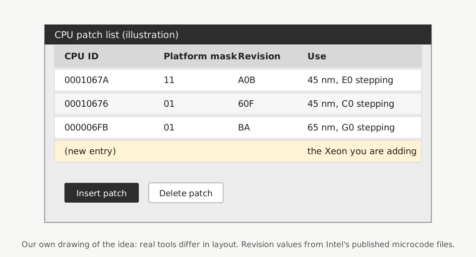
Before you change anything, write down every row. Then compare with MC Extractor's list of the same file, which does show the platform mask. You want to know three things:
- Which rows serve the CPU that is in the board now. Those stay, no matter what.
- Whether a row for your Xeon's CPUID already exists. A row with the right CPUID but a desktop mask such as 11 does not count.
- Which rows serve CPUs you will never install in this board.
Step 6: make room if you need to
The BIOS image has a fixed size, and the microcode area has only so much free space in it. Adding one 8 KB patch may fit; adding three patches often will not. If the insert fails for lack of space, remove patches before you add.
Rules for choosing what goes:
- Keep the patch for the CPU in the board now, and for any chip you might fall back to while you test the Xeon. If the Xeon refuses to boot, the old chip has to work.
- Remove only rows you can identify. Look each CPUID up in Intel's specification updates or Intel's repository before you delete it, and note what you removed.
- Never empty the table. Leave every patch for chips you might plausibly run.
In MMTool, select the row, choose the delete option and click Apply. Forum users note that module positions inside the image can change after patches are deleted or inserted, so verify the saved file rather than assuming it came out as planned.
Step 7: insert the patch and save under a new name
Choose the insert option on the CPU Patch tab, browse to your single-patch file and click Apply. The new row should
appear with the CPU ID and revision you expect. Save the image under a new file name, for example MODDED.ROM, and leave
the original untouched.
Now check the result in three ways:
- Reopen
MODDED.ROMin MMTool and confirm the row list matches your plan: old CPU's patches present, Xeon patch present, removed rows gone. - Open the file in MC Extractor and check that the new patch shows the right CPUID, the right platform mask and no checksum warnings.
- Compare file sizes.
MODDED.ROMmust be exactly the size of the backup and of the chip. If it is not, stop and find out why before you flash.
Step 8: flash it with the board's own tool
Use the flasher the board maker documents for your board, and run it with as little else going on as possible. On ASUS boards of this era the manual (the P5Q WS one is typical) lists three:
| Tool | Where it runs | Notes |
|---|---|---|
| EZ Flash 2 | Inside the BIOS (Alt+F2 at POST, or the Tools menu) | Reads from a FAT16 or FAT32 stick with one partition |
| AFUDOS | DOS boot stick | afudos /iMODDED.ROM |
| ASUS Update | Windows | Supported by ASUS, but we prefer the BIOS or DOS route |
MSI boards with M-Flash in the setup menu flash from a USB stick the same way. AMI also makes a Windows version of its flasher, AFUWIN. Gigabyte's Q-Flash belongs to Gigabyte boards, and most Gigabyte boards of this era run Award firmware; for those, see the Award and Phoenix-Award guide.
afudos /iMODDED.ROM
While it writes, leave the machine alone. ASUS's manual is blunt about it: do not shut down or reset the system during the update. If the lights flicker, you will be glad of that UPS.
Step 9: first boot with the patch
Power off, clear the CMOS (jumper or battery out for a minute, as page 4 of the LGA 771 to 775 guide describes) and load the setup defaults. Boot with the CPU you used for flashing first, if you can, to prove the image works. Then fit the Xeon.
To confirm that the BIOS, and not the operating system, loaded the patch, boot a Linux live stick with the kernel
parameter dis_ucode_ldr, which turns off the OS microcode loader. The revision you see is then the one the BIOS
applied:
grep -m1 microcode /proc/cpuinfo
For the E0 patch from Intel's repository it should read 0xa0b. If the board still complains or the
machine is unstable, page 5 of the LGA guide works through the usual suspects in order.
If the board will not start
Do not panic and do not keep flashing random files. Work through these in order:
- CrashFree BIOS 3 (ASUS). ASUS documents it as an automatic recovery from the support DVD, a floppy or a USB
stick when the BIOS is corrupted. The stick must be FAT16 or FAT32 with one partition and, per the manual, smaller
than 8 GB. The file has to carry the name the board expects; the P5Q WS manual's example reads
P5Q-WS.ROM. Put your backup or the official file on it, not the modified one. - A spare chip. If the BIOS chip on your board sits in a socket, a spare programmed with your backup can be swapped in with the power off.
- An SPI programmer. Many boards of this era keep the BIOS in an 8-pin SPI flash chip, soldered or socketed. A CH341A programmer with a SOIC8 clip can write your backup straight back. Read reading a BIOS chip with a CH341A programmer before the day you need it. Some older boards use a square PLCC chip instead, which the CH341A does not handle.
Keep the backup files, the modified image and a text note of what you changed in one folder. The next time the board maker releases a BIOS, you will redo Steps 2 to 7 on the new file, and that note turns a fiddly evening into a short one.

Tessa covers BIOS images, microcode and firmware recovery. Her rule for every flash: two backups of the original image, a known recovery path, and nothing else running on that power strip.