How to install an LGA 771 Xeon in an LGA 775 board, step by step
This page is the hands-on part of the guide. It assumes you have already confirmed that your board's chipset and BIOS can run the chip (page 2) and that you have picked a Xeon whose bus speed, power class and stepping match it (page 3). If either is still an open question, settle it first. Nothing below makes an unsupported board support a Xeon. The steps only remove the physical obstacles.
Set aside an unhurried hour at a clear, well-lit desk. Most of that time goes into looking closely, not cutting.
What you need
- The Xeon you chose and an LGA 771 to 775 adapter sticker, plus a spare sticker in case the first one goes on crooked.
- Your current LGA 775 processor. You need a chip the BIOS already runs to flash the update in step 1.
- A precision hobby knife with a fresh, sharp blade. A dull blade tears plastic instead of cutting it, and tearing is when hands slip.
- Fine tweezers, ideally ESD-safe ones, for lifting cut plastic out of the socket.
- A lighted magnifier or a loupe, and a desk lamp you can angle low across the socket.
- An anti-static wrist strap, and an anti-static mat or the bag the Xeon arrived in to set chips on.
- 99 percent isopropyl alcohol and lint-free wipes to clean old paste off the cooler and the heat spreader.
- Fresh non-conductive thermal paste for the new chip.
- A USB stick for the BIOS file, and your board's manual (the PDF from the maker's support page is fine) for the CMOS jumper location.
The Parts bin picks are matched to these jobs from their specifications and published reviews. We have not run them through any tests of our own.
The steps
Step 1: Update the BIOS and confirm support
Do this with the old LGA 775 chip still in the socket. Once the tabs are cut and the Xeon is in, you may not get far enough to flash anything.
- Identify the exact board model and revision. The revision matters, because a "rev 1.0" and a "rev 2.0" board can have different BIOS files and different CPU lists. Our guide on checking whether a motherboard supports a processor covers the sticker, the BIOS screen and the software methods.
- Open the CPU support list on the maker's support page and find the desktop chip that matches your Xeon: the same core, the same FSB and ideally the same stepping. For an E5450 that means a Q9650 or another 45 nm quad at 1333 FSB. Note the BIOS version that added it.
- Back up the current BIOS with the board's own flash utility or a BIOS backup tool, and copy the file somewhere off the machine.
- Flash the latest BIOS from the board maker with the method the manual describes (a built-in flash tool in setup, a DOS utility or a Windows utility). Do not interrupt it, and do not flash during a storm or on a shaky power strip.
- If the board needs a microcode entry added for the Xeon, do that now as well, while the old chip still boots. The Xeon microcode guide explains how to tell whether you need one.
Before you shut down, take a photo of any BIOS screens with settings you changed from the defaults, such as SATA mode, boot order or an overclock. Then set any overclock back to stock. Step 5 wipes everything anyway, and a photo is quicker than remembering.
Step 2: Remove the two socket key tabs
Shut down, switch off the power supply and pull the cord. Clip on the wrist strap. Remove the cooler, wipe the old paste off its base with isopropyl alcohol, and take out the old CPU by its edges. Put the chip on the mat or in its bag.
You can work with the board in the case if the case lies flat on its side and the socket is easy to reach. If anything around the socket gets in the way of a straight cut, take the board out. Open the load lever and lift the load plate so the socket body is fully exposed.
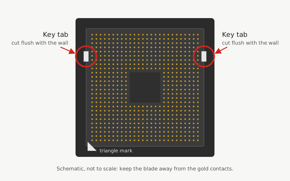
The two key tabs are small plastic bumps moulded into the inner walls of the socket body. On a desktop chip they fit into the notches on the package edge. An LGA 771 Xeon has its notches in different places, so the tabs stop it from dropping in. Removing them is the whole mechanical change to the board.
- Angle the lamp low so it lights the socket floor and you can see the contacts clearly.
- Rest the heel of your cutting hand on something solid, such as the edge of the board or the case, so the blade can't jump.
- Set the blade against the tab where it meets the wall and cut it flush with the wall in small, shallow passes. Keep the edge moving away from the contact field, toward the socket wall, never toward the middle of the socket.
- Never touch the contacts with the blade, the tweezers or a finger, and never press down on them. They are fine spring contacts, and once bent out of line they are very hard to put back.
- When the tab comes free, pick it out with the tweezers right away. Don't blow into the socket, because breath carries moisture, and don't brush across the contacts.
- Repeat for the second tab.
Now inspect under the magnifier with the lamp low. Look for any plastic left in the contact field, a raised edge where the tab was, and any contact that sits out of line with its neighbours. A bent contact catches the light differently from the regular pattern around it, which is much easier to see at a low angle than from straight above. If you find a sliver of plastic, lift it out with the tweezers. Don't chase it across the contacts.
The tabs only ever controlled orientation, so the socket still accepts LGA 775 processors afterwards. From now on the only orientation guide is the triangle mark, for both kinds of chip. If you are not continuing straight away, close the load plate to cover the contacts.
Step 3: Attach the adapter sticker
The sticker is a thin film shaped to the pad area on the underside of the CPU. Its job is to reroute a small number of contacts so the Xeon's pinout lines up with what an LGA 775 board expects. Page 1 explains why that is needed.
- Put the Xeon on the mat with the gold pads facing up, holding it only by the edges. If the pads have fingerprints or grime, wipe them gently with isopropyl alcohol on a lint-free wipe and let them dry completely.
- Find the gold triangle on one corner of the CPU. The sticker has its own triangle mark, which goes at that same corner.
- Hold the sticker by its edges and peel the backing slowly. Don't touch the adhesive side or its contacts with your fingers.
- Line the sticker up with the edges of the pad area before any part of it touches the chip. Then lower it flat, all at once.
- Lay the backing paper over it and press evenly with a fingertip, working from the middle outward.
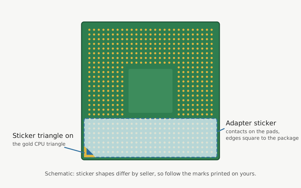
Check the result under the magnifier. The sticker should sit square with the pad grid, with no lifted corners, wrinkles or trapped dust, and its contacts should sit on the gold lands they are meant to cover. Never stack a second sticker on top of a bad one, because the extra layer changes how the socket contacts press on the chip. If the first one went on crooked, peel it off slowly, clean the adhesive residue off the pads with isopropyl alcohol, let them dry and fit the spare.
Step 4: Seat the CPU
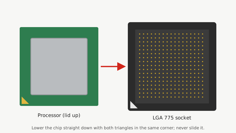
With the load plate open, hold the Xeon by its edges, sticker side down. Turn it so the gold triangle on the CPU sits at the same corner as the triangle marked on the socket frame. Lower it straight down into the socket without sliding it. It should settle flat under its own weight with no pressure from you.
Check the triangle a second time. With the key tabs gone, a chip turned the wrong way can also sit flat, and nothing on the socket will stop you closing the plate on it.
Close the load plate and press the lever down under its retention hook. Some resistance is normal, because the lever is what presses the chip onto the contacts. If it feels much stiffer than it did with the old processor, stop, lift the plate and check that the chip and sticker sit flat.
Clean the Xeon's heat spreader with isopropyl alcohol, apply fresh paste and mount the cooler. Our repasting walkthrough covers paste amounts and mounting pressure. On Intel push-pin coolers, press down opposite corners in pairs and check from the back of the board that all four pins have locked. Reconnect the CPU fan and the 4-pin or 8-pin ATX12V power plug near the socket.
Step 5: Clear the CMOS and load defaults
The board still remembers settings made for the old processor, and some of them, such as a manual FSB or voltage, can stop the Xeon from starting. Clear them completely.
- Keep the power cord pulled out. While it is plugged in, the board still gets standby power from the supply, and board manuals tell you to unplug before clearing CMOS.
- Find the clear-CMOS jumper in the manual. It goes by names such as CLR_CMOS, CLRTC or JBAT1. Move the cap to the clear position for about ten seconds, then put it back on the normal pins. Some boards have a clear-CMOS button instead.
- If you can't find the jumper, take the coin cell out of its holder for a few minutes, then put it back the right way up.
- Make sure the jumper is back in its normal position before you power on. Left on the clear pins, it can stop the board from booting.
- Plug in, power on and enter setup. Choose the option called Load Optimized Defaults or Load Setup Defaults, depending on the board.
- Set the date and time, the boot drive and the SATA mode your operating system was installed with (AHCI or IDE). Loading defaults can change the SATA mode, and a mismatch makes an installed Windows fail to start, which looks like a CPU problem but isn't. Save and exit.
Owners commonly report that some boards switch off and on again once or twice after a CMOS clear before the first picture appears. Give it a minute before deciding it won't POST.
Step 6: First boot checks
Start in the BIOS setup, before any operating system loads:
- The CPU name should be the Xeon's own model name, because the chip reports its name string itself.
- The speed should match the arithmetic from page 3. An E5450 should show a 333 MHz bus, a multiplier of 9 and 3.00 GHz. A 266 MHz bus or a lower multiplier means something is wrong, and page 5 covers it.
- If the setup screens show a core count, it should be four for a 5400 series chip and two for a 5200.
- In the hardware monitor, leave the machine idling in setup for a few minutes and note the CPU temperature. With the same cooler, it should land close to what the old chip showed. A big jump points at the cooler mount or the paste.
- Watch for any POST message about an unknown CPU, a BIOS update or microcode. Write down the exact wording and go to page 5 before you carry on.
Then boot the operating system and confirm the same facts from there. On Windows, in PowerShell:
Get-CimInstance Win32_Processor | Select-Object Name, NumberOfCores, MaxClockSpeed
On Linux:
lscpu | grep -E 'Model name|^CPU\(s\)|Stepping'
grep -m1 microcode /proc/cpuinfo
The stepping line should read 6 for a C0 chip (CPUID 10676) and 10 for an E0 (CPUID 1067A). Our guide to finding the CPUID, stepping or sSpec decodes the rest.
Finish with a short stress test of 10 to 15 minutes: Prime95's small FFT test on Windows, or stress-ng --cpu 4 --timeout 15m on Linux with sensors running in a second terminal. Watch the temperature the whole time. A reading that rises and then levels off is normal. One that keeps climbing without levelling, or a crash, an error or a sudden restart, means you stop the test and go to page 5.
A clean run means the mechanical part of the mod is done. Put the old Core 2 and the spare sticker in an anti-static bag and keep them. If page 5 ever sends you back to reflash the BIOS, the old chip is the one that will boot to do it.

Marek writes the socket-mod and Xeon pages. He likes boards with too many jumpers, keeps a drawer of LGA 775 chips sorted by stepping, and reads Intel spec updates the way other people read box scores.